Choosing a Mining Expansion Shell Anchor Bolt is a ground-control decision, not a catalogue exercise. The correct bolt must match the rock mass, excavation geometry, expected load, and installation conditions. A strong-looking bolt can still perform poorly in fractured or wet ground.
Professor Evert Hoek, a leading rock-engineering authority, has emphasized, “The rock mass is the material.” That principle should guide every selection. Examine core logs, joint spacing, water seepage, and visible roof movement before comparing bolt specifications. Measure the borehole diameter carefully. Check whether the shell expands evenly inside the drilled hole. Confirm that the bolt length reaches competent rock, rather than stopping in loose fragments.
Load capacity matters, but it is not the only measure. Consider thread strength, plate size, corrosion protection, tightening torque, and compatibility with resin, mesh, or shotcrete. A bolt rated highly in a laboratory may behave differently underground. Field pull testing can reveal that gap.
Keep the installation practical. If operators cannot insert, tension, and inspect the bolt consistently, the design is incomplete. Small errors matter. Dust can reduce shell grip. An oversized hole can weaken anchorage. Water can accelerate corrosion.
I would not select a Mining Expansion Shell Anchor Bolt from strength figures alone. That approach is tempting, but incomplete. Review the geological evidence, consult qualified ground-control professionals, and compare verified test data. Reassess the choice when mining depth, stress, or moisture conditions change. The safest selection is the one that remains understandable, installable, and inspectable in the real working environment.
How to Choose Mining Expansion Shell Anchor Bolts?
Understanding the Structure and Working Principles of Mining Expansion Shell Anchor Bolts
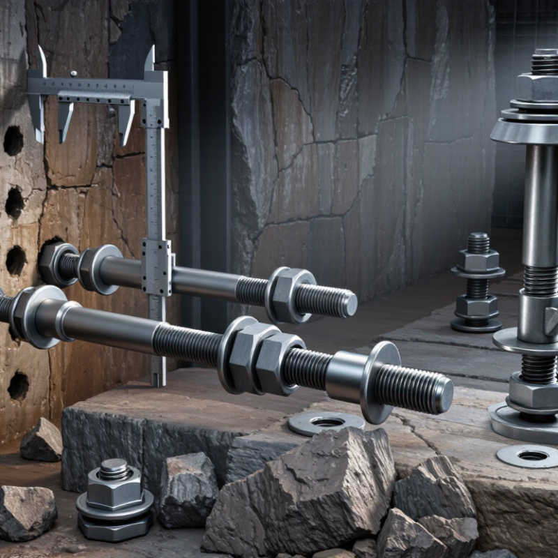
A mining expansion shell anchor bolt usually contains a threaded steel bolt, expansion shell, tapered cone, washer, and nut. The shell grips. When the nut tightens, the bolt pulls the cone into the shell. This action forces the shell leaves against the borehole wall. Friction and mechanical interlock then transfer load into the surrounding rock.
Selection should match the rock strength, joint condition, hole diameter, anchorage depth, and expected load. Competent rock may support shorter anchors, while fractured or layered rock often requires deeper engagement. Check static and dynamic loading separately. Water also matters, because corrosion can reduce bolt capacity over time. Galvanized or corrosion-resistant protection may be appropriate, but the site environment decides.
Installation quality controls the working principle. Drill a clean, correctly sized hole, then insert the assembly to the specified depth. Apply the engineer’s torque range with a calibrated tool. Excessive torque can damage the shell or stretch the bolt. Insufficient torque may leave weak contact with the rock. A torque value alone is not enough. Field pull tests, visual checks, and periodic inspections provide stronger evidence. Small details matter. I have seen well-designed anchors perform poorly because holes were oversized or filled with loose dust. Load changes. Ground movement should be reviewed regularly, not assumed away.
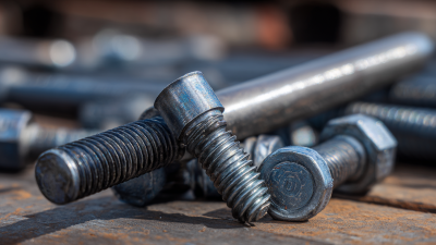
An expansion shell anchor transfers load through friction against the borehole wall. It performs best in competent, relatively dry rock with stable hole geometry. In fractured shale, clay-bearing seams, or heavily weathered zones, shell seating may become unreliable. The bolt may appear tight but lose capacity during blasting or movement.
Use core logs, face mapping, and borehole observations together. Record RQD, joint spacing, aperture, water, and infill.
The Q-system, developed by the Norwegian Geotechnical Institute, rates rock quality from 0.001 to 1,000. Very low Q values indicate poor ground and usually demand reinforced systems beyond a simple expansion shell.
ISRM guidance also recommends checking discontinuity orientation, persistence, and shear strength before support selection. These details matter underground.
ASTM F432 provides mechanical requirements for roof and rock bolts, but installation quality remains decisive. Verify torque, embedment, plate contact, and pull-test results at representative locations.
Many operations use proof testing near the planned working load, although the exact value should follow the engineer’s design. In wet headings, inspect corrosion exposure and drainage.
In burst-prone ground, static capacity alone is insufficient; energy absorption and deformation tolerance need review.
I have seen designs fail because the rock class was correct on paper, but the borehole was oversized after drilling. That uncomfortable detail deserves more attention.
MSHA ground-control accident reports repeatedly link serious incidents with unstable strata and inadequate support decisions, reinforcing the need for field verification rather than catalogue selection.
Selecting the correct bolt material starts with the rock, moisture, and expected service life. High-strength carbon steel suits many dry underground areas, but wet headings need corrosion protection. Galvanized or coated bolts can reduce surface rust, while stainless steel may suit aggressive environments. However, strength and installation behavior must be checked together.
Water changes everything.
Bolt dimensions should match the design load, borehole diameter, and required anchorage length. A larger diameter is not automatically safer. An M20 bolt may perform poorly if the hole is oversized or the shell cannot grip sound rock.
Field crews should measure hole depth, inspect fractured zones, and verify thread engagement before installation. Keep the bearing plate firmly against the surface.
Fit matters.
Expansion shell design controls how the load transfers into the rock. Two-leaf shells can provide practical contact in variable boreholes, while wedge-style shells may deliver stronger localized gripping. Serrated contact surfaces can improve resistance against rotation, but they may damage weak rock during tightening.
Installation torque should follow tested engineering data, not guesswork. On site inspections, I have seen reliable bolts fail because dust remained in the borehole or the shell was set in broken rock.
That detail is easy to overlook.
Load testing, pull testing, and documented inspection records help confirm whether the selected material, dimensions, and shell geometry work together. When ground conditions change, the original selection deserves another review.
Choosing mining expansion shell anchor bolts starts with the rock, not the catalogue. Underground faces may contain fractured shale, wet seams, or competent granite. Each condition changes drilling accuracy, shell expansion, and pull-out resistance. A site engineer should review core logs, geological mapping, and recent convergence readings before selecting bolt diameter and embedment. I have learned that a clean-looking wall can hide weak bedding planes.
Installation quality directly affects load performance. Rotary-percussive drilling usually suits hard rock, but excessive vibration can enlarge the hole. The drilled diameter must match the anchor specification. Workers should clean each hole, check its depth, and seat the shell against sound rock. A calibrated torque wrench helps prevent under-tightening and thread damage. In wet headings, drainage and corrosion protection deserve attention. Small mistakes become expensive underground.
Load-bearing checks should include bolt tension, shear, plate bearing, spacing, and edge distance. Dynamic loads from blasting or equipment movement may exceed simple static estimates. Pull tests on representative anchors can confirm actual capacity, especially where geology varies sharply. Designers should apply suitable safety factors and document every test result. No calculation is perfect. Field conditions often change faster than drawings. Regular inspection can reveal loose plates, corrosion, or developing cracks before support performance declines.
Installed mining expansion shell anchor bolts need regular inspection, not occasional visual checks. Examine the nut, washer, bearing plate, and exposed thread for movement, distortion, or corrosion. The plate should sit firmly against sound rock, without gaps or fresh cracking around the hole. Water staining may indicate seepage that is weakening the installation.
Use project-approved torque values and calibrated tools when checking tightness. A loose nut does not always mean the bolt has failed. It may reflect rock movement, installation error, or damaged threads. Torque alone cannot confirm capacity. Qualified personnel should review suspicious anchors and arrange pull testing when required. Record each bolt’s location, condition, inspection date, and any unusual sounds or movement.
Maintenance should include controlling water, removing loose scale, and protecting exposed steel with an approved system. Do not weld, heat, or force a seized nut. These actions can reduce bolt performance. Replacement requires area control and an engineering assessment. Remove the damaged anchor carefully, inspect the surrounding rock, and confirm whether the original hole remains suitable. In many cases, a new hole, longer bolt, or different anchorage depth is necessary. Install the replacement according to the specified embedment, torque, and plate contact requirements. Proof-test critical replacements and update the ground-support record. Field documentation is often incomplete, and that weakness deserves attention.